2 x 72 Belt Grinder
👉If you find any of this information useful, please be sure to subscribe to the Making Stuff channel. It doesn't cost you anything but a click! Click Here.
Making a 2 x 72 belt grinder has been one of those projects that was always at the top of my project list, but I never really got around to making it. I have always wanted a 2 x 72 belt grinder and I knew it would come in handy if there was one in the shop. But with a pretty hefty purchase price it just wasn't going to happen any time soon.
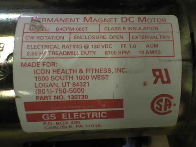
Then one day I was tearing my shop apart to repair an outer wall and I found a motor that I had taken out of an old treadmill that some one had given to me for free. The treadmill didn't work of course, but that didn't stop me from ripping the motor and controller out of it before throwing away the rest of the useless parts. It was obvious that the controller was beyond repair but the motor still worked. The only problem was that the motor was 130VDC and I had no idea what I was going to do with a 130VDC motor. So it went in a pile of old junk and sat there for several years.
The forgotten motor resurfaced when the repairs were done to the outer wall. After closer inspection, I noticed that it was a 2.5HP motor. Most of the free motors that I get have little or no markings. But this one has all the information that one would want to know about the motor printed on a label. I often get asked questions about the motors that I use in my projects and most of the time I don't know volt, amps, watts model number, etc. For those of you that want to know this information this is your lucky day.
This would work great for a belt grinder if I could only find some way to controll the motor without using ten 12v car batteries. So I did some research and found that the motor controller was called an MC-60 and quite common. Used MC-60 controllers could be had on eBay for around $30, new ones with warranty can be purchased on Amazon. This is exactly what I needed to get the project started! I had seen belt grinder kits that used 2HP three phase motors and a VFD to control the motor, but these can be quite expensive. To purchase these parts on eBay can cost several hundred dollars. I figure for only $30 it was worth a shot to at least try it out and see how well the motor would work. The only other part needed was a 10k potenetiometer to controll the motor speed.
The build for this is quite simple. For the base I used 2 inch square steel tubing with a wall thickness of .187 inch. It is important to use .187 inch wall thickness so that the inserts will make a tight fit. The insert pieces for the platen and idle roller are 1.5 inch square steel tubing. I obtained all of the steel for this project at my local welding shop. They often sell me the cut offs and scrap at a discount price. But for this project I had to purchase so steel off the shelf which cost more. The welding shop also cut the platen out on a CNC plasma cutter. I figured the extra cost would be worth it rather than spending the time to get it just right by using hand tools and a drill press. The total cost for the steel and CNC works was $100.
Once I got the base welded together, I welded a 2.5 inch piece of pipe to the flywheel that I got from the local scrap yard for 50 cents. I fired up the motor and got it to spin at about half speed. When I stopped the motor, the inertia from the flywheel kept it spinning. It spun right off the shaft of the motor and went rolling across the shop floor. It was then that I noticed that the flywheel was left hand threaded. This was a problem because I needed the motor to turn this direction so that the belt spins down and away from me. I had not welded the motor mount yet, so I decided that the easiest thing to do would be to run the belt on the right side of the machine instead of left. I have no idea why I chose to run the belt on the left at first other than all the other machines I had seen had the belts on the left.
The next step was to mount the rollers to the platten and idle adjust bar. I got the rollers from eBay for $34. They are made by Oregon Knife Works and are very good quality. There where aluminum rollers for $89 but I chose to get the cheaper plastic rollers. I could always upgrade later if I need to. So far the plastic ones work great. I figured that for $34 it was worth it rather than trying to make rollers and try to balance them. The idle roller also has a slight crown. This is for adjusting how the belt tracks. I knew it would be a PITA to try and do this myself, so it just made since to spend a few bucks on the rollers.
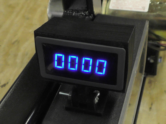
I also wanted to put a tachometer on the belt grinder. This treadmill motor will run at 6700 RPMS max speed which is about twice as fast as most AC motors. To be honest, 6700 RPMS will just tear up the belts and roller bearings so there is no need to run it that fast. So far I have been able to run it under 3000 RPM and the grinder worked just fine. I am thinking about putting a limiting resistor on the circuit so the motor wont wun at full speed. The tachometer was purchased on Amazon for $16. It came with the hall effect sensor and the LED read out. I used an old wall wart for the DC power supply to power the tachometer and hall effect sensor. I 3D printed a case for the display which can be found here. Another feature of the controller is that it will detect when the motor slows down under load, and try to compensate by giving it more power. THis is nice for when I push a workpiece into the belt really hard. Instead of the machine lagging or slowing down, it speeds up. This was a nice and unexpected feature from the MC-60 controller.
All in all the project turned out quite well. I am happy with the belt grinder and I have less than $200 in the whole project. If you plan on building one, there are a few things you want to make sure of before you start. First is to make sure you know which way your motor is turning and mount the belts on the correct side of the machine. Also, make sure to keep all of the pulleys square to each other. If they are not square, you will have belt traking problems which could also cause the belt to rub the side of the machine. The belt grinder in the video doesn't have enough clearance at the base which causes the belt to rub if it is not adjusted correctly. So make sure you have enough clearance at the base.
The Sketchup 3D drawing for this project is available to all Maker+ patrons at Patreon.com.
* Here is the BOM for this project:
- 2" x 72" abrasive belts
- 36" - 2 inch square tubing .187 wall thickness
- 28" - 1.5 inch square steel tubing
- 48" - 3 inch steel angle iron .250 inch thick
- 1- Platen CNC cut out of 3/8 inch steel plate
- 1 - 4 inch x 6 inch .250 thick steel plate
- 10 - inches of 3/4 x 3/8 steel bar
- 1 - 4 inch x 6 inch .250 thick steel plate
- 1 - CRC cutting oil
- 5 - inches of 2.5 inch pipe for drive roller
- 1 - Treadmill motor
- 1 - MC-60 motor controller
- 1 - 10K potentiometer
- 1 - Set of belt grinder rollers
- 1 - Blue LED Tachometer
- 1 - 3D printed mount for tachometer
- 1 - 9V power supply for tachometer
- 1 - Power switch
- 1 - Project enclosure to hold electronics - https://www.polycase.com/dc-58f
* This web site uses affiliate links on some product links. This provides a way for the website to earn a very, very small commission (at no cost to you) which helps pay for this website and the free information you are currently enjoying.